


Hong Kong International: the airport that changed the world

Project overview
From masterplanning to masterpiece
Now well into its third decade of operation, Hong Kong International Airport has continuously been named among the world’s best by customers and passengers. The airport was required to enable Hong Kong’s continued growth as an international commercial centre: the former Kai Tak Airport in central Kong Kong was unable to expand.
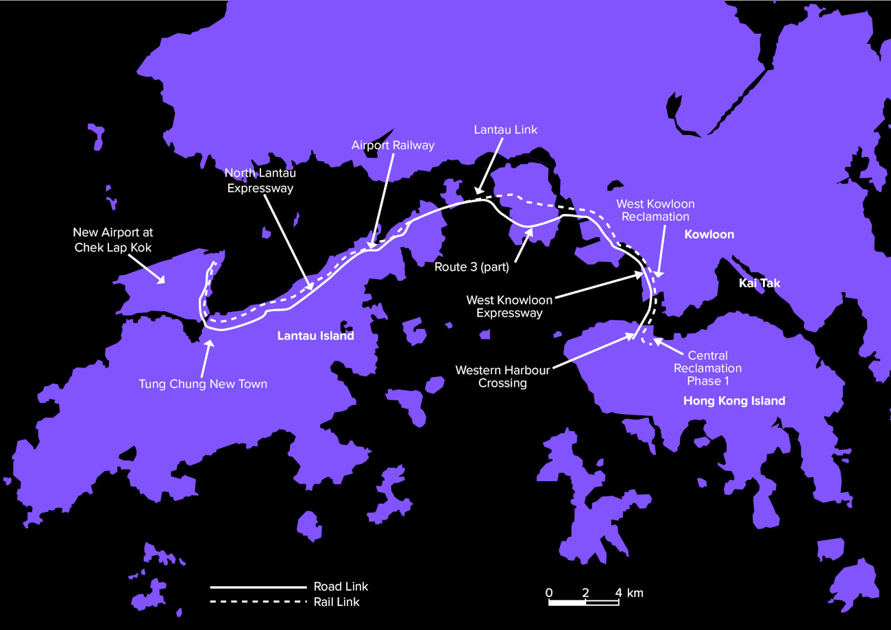
On 4 July 1991 the Chinese and British governments agreed to move forward with the largest airport development in the world. Located adjacent to Lantau Island approximately 30km west of central Hong Kong, it required two smaller offlying islands to be levelled and joined together, plus the reclamation of more than 1,000ha of land from the sea. The new terminal building measured 1.2km long, setting new and widely imitated standards for passenger experience, retail, operational efficiency and aircraft docking. Its twin runways and airfield were state-of-the-art.
To enable rapid transit, the new airport was connected to central Hong Kong by 22km of new highways and a high speed railway, involving construction of the world’s longest road and rail suspension bridge.
In totality the airport was among the biggest engineering projects of the 20th century. Politicians set a seemingly impossible deadline of just seven years.
Mott MacDonald was involved from the very start. Leading a multidisciplinary design team and managing the overall programme, we helped deliver what many thought was unachievable: the airport opened on schedule on 6 July 1998. And we have remained closely involved with the airport ever since, helping the airport authority expand and adapt to growing demand.
This special report tells the full story of our involvement, from start to present: from the 1980s studies that outlined options for relocating the airport, to the opening of the airport’s third runway in November 2024, which equips Hong Kong International Airport to meet the demands of the coming decade and beyond.
Quick links
- Pushing the limits – the HKIA strategic plan
- A new model for airport design
- Mission impossible?
- Foundations for innovation
- New environmental standards
- Tsing Ma Bridge
- Keeping HKIA at the leading edge
1. Pushing the limits
Booming economic growth meant that, as Hong Kong entered the 1980s, its transport infrastructure was struggling to keep pace with demand. Its airport was especially under pressure.
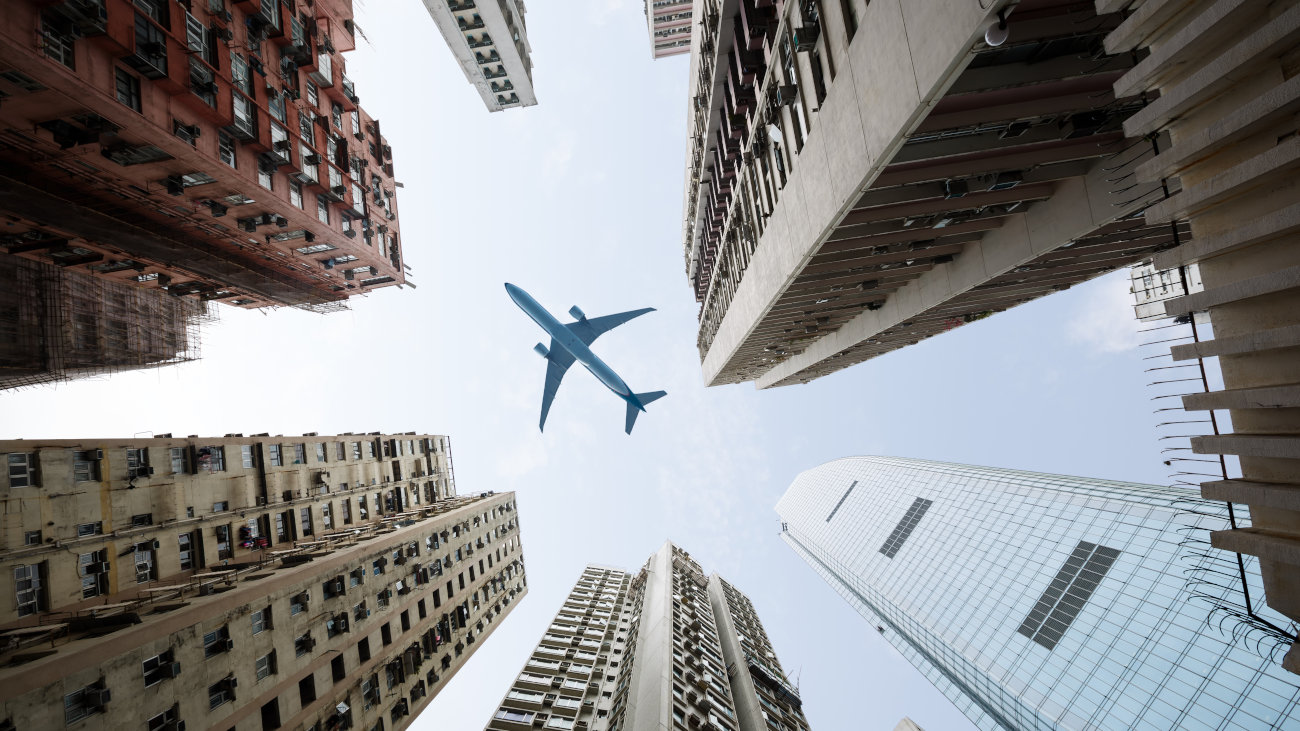
Hong Kong’s Kai Tak International Airport, built in 1925, was operating well beyond its design capacity. It was sandwiched between high rise buildings and rugged mountains: it was famous among pilots for being the most difficult landing of any airport in the world.
Staff in our Hong Kong office were regular flyers and knew both in principle and practice that the airport’s inability to grow would constrain Hong Kong’s ongoing development as a world leader in banking and commerce.
Early presence in Hong Kong
The company’s earliest project in the territory was a proposed expansion of Hok Un power station in 1934 by Preece, Cardew & Rider, which joined Mott MacDonald in 1994; we established a permanent office in Hong Kong in 1954 when undertaking the feasibility study for the first tunnel crossing Victoria Harbour to connect Hong Kong and Kowloon.
-
1934earliest project in the territory
-
1954establishing a permanent office
Lantau Island to the west of Hong Kong was, at the time, relatively undeveloped. Our team saw its potential as a site not just for the airport but for the broader expansion of Hong Kong’s population and economy, thanks to its size and proximity. We carried out a range of development studies for the area, including potential connections to central Hong Kong.
“Work had been done on various studies and master plans. The only way to get to Lantau was by a very long suspension bridge. We’d previously designed the Forth and Severn Bridges in the UK, which were record-setting in their day. We brought that experience and got involved early on,” says Robin Whalley. Now retired, in the 1980s Robin was project director for Mott MacDonald, going on to programme manage construction of the airport.
Robin led our work for the Provisional Airport Authority on what could be described as the most important study it would ever undertake – the Ports and Airports Development Strategy, known as PADS. The comprehensive masterplan led to a series of 10 mega projects known as the Airport Core Programme. It concluded that the north shore of Lantau was the best location for the new airport. But to create a level area of sufficient size, two small islands, Chek Lap Kok and Lam Chau, had to be levelled, and the area between them reclaimed from the sea.
“Projects making up the airport core programme were absolutely amazing. We achieved them, collectively, in a very short space of time – less than a decade,” notes Dr Anne Kerr, Asia executive advisor.
Hong Kong International Airport Core Programme projects
2. A new model for airport design
Combining operational experience with engineering skill and architectural genius was the secret to designing the world’s best airport in record time.
In March 1992 the Mott Consortium beat eight other bidders to win the international design competition for a new world class airport at Lantau. The unique design was the product of an equally unique collaboration between architect Sir Norman Foster & Partners, Mott Connell – our multidisciplinary engineering partnership with Australian engineer John Connell – consultant Arup, and airport operator BAA.
Bringing these essential skillsets together into a single, joined-up delivery team was an industry first. Removing organisational barriers between operational, architectural and engineering inputs enabled the design to be optimised not just for delivery but for use and customer experience.
“We were a winning team,” says Mike Barker, former head of Mott MacDonald’s structural design team, now retired. “The project was large enough to bring those prominent firms together with complementary expertise, to provide a team which had absolutely no weaknesses.”


The entire programme was an exercise in innovation and benefitted from the multidisciplinary team’s novel ideas. We suggested the idea of an in-town check-in service, which was a new concept at the time. This system allows travellers to check in during the morning, spend the day working or sightseeing in the city, and then head out to the airport without having to struggle with their luggage. The concept has since been adopted, with success, around the world.
However, it was the terminal building that captured the attention of design competition judges. It provided all the diverse functions required in a single, vast but elegant building, measuring 1.2km long and with a footprint of 516,000m2. The whole building was open plan, giving staff and passengers a sense of space that was unprecedented in airport buildings, while floor to ceiling glazed facades allowed travellers to see the spectacle of planes landing, taking off and taxiing. The whole building was unified by a lightweight vaulted roof. Hong Kong airport revolutionised the design approach, creating a new airport form for the modern era.
“If you can get a design concept that's great and simple, the art lies in retaining that as the design evolves,” says Mike.
That was possible thanks to the unique capabilities of the integrated design team. Foster’s architectural vision was balanced by BAA’s functional focus, and enabled by Mott Connell’s deep structural understanding. Between them, they ensured that the design was elegant whilst also functional. This included ensuring efficient areas for processing passengers and baggage, concourses for accessing the planes, ground transportation for arrivals and departures, and attractive retail areas to generate revenue.
Mott Connell designed the unique supporting structure and foundations, solving complex engineering challenges.
“A lot of the value that we brought into the building was to make sure that the structure supporting the roof was as efficient as possible,” says Mike. Beneath the steel framed, barrel-vaulted roof was a grid of heavily reinforced circular concrete columns with floor plates of exposed concrete spanning between them. All the airport’s service equipment such as power and ventilation had to be hidden to maintain the elegant design concept. It was a very difficult proposition for the structural engineers who had to ensure that the vision became reality.
3. Mission impossible?
Deep structural understanding, the development of groundbreaking software, and effective standardisation were required to bring an “architectural sculpture” to reality.
Form and function were perfectly aligned in the creation of the terminal building. “It was the biggest building under construction in the world at the time. Its floor area is equivalent to about 10 of the world’s largest stadiums,” says Paul Bates, who was one of three lead structural engineers working on the terminal building. Based in Hong Kong, Paul worked on the project throughout design and construction from 1992 to 1998.
“When we went out to tender there were about 340,000 drawings in total. If you’d laid them end to end, it would work out about 400km long.”
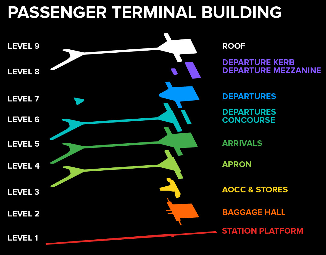
At the eastern end of the terminal is a multi-level building containing departures and arrivals halls, baggage handling and other core functions. It funnels into a slim, 600m long central concourse, which forks at its western end. The terminal is just over 1.2km long and has a 5km perimeter.
Section through the airport
“The reticulated steel diagrid roof arches are supported by circular section reinforced concrete columns on a 36m grid,” says Paul. Columns vary from 1.2m to 2.5m in diameter and were cast monolithically with the reinforced concrete floor slabs. In the lower levels, stability and support were provided by a combination reinforced concrete shear walls and additional columns arranged on subgrids of 12m and 9m by 6m.
Hong Kong experiences powerful typhoon winds and the terminal building was therefore designed to take high lateral loading. Additionally, the columns had to cope with the outward thrust exerted by the roof arches: unless tied, arches tend to sag and spread, exerting horizontal as well as downward force. The most complex case was for the columns along the building perimeter. “These huge arches create enormous horizontal thrust which is most extreme at the edges of the building,” says Paul. Therefore, around the perimeter of the building in particular the diameter of some columns was increased. Each was heavily reinforced.


Members of the design dream team on site: Paul Bates, John Goodsir, Chris Sparrow and David Mepham
“When I started the job we needed to know what the load was on the columns, in order to design them: we asked the roof designer, Arup, for figures. But they needed to know the stiffness of our columns was going to be in order to design the roof.”
It was a chicken and egg situation that Paul’s team resolved by developing a range of reinforcement designs. “We could change column stiffness to withstand different roof loads,” Paul recalls.
“We estimated loading values across the building, which enabled us to calculate the column stiffnesses required, and design the column grid. Arup could then design the roof. They ran analysis and fed the loading back to us so that we could fine tune the column design.”
Groundbreaking analysis
Mott Connell put one of its best structural engineers, John Goodsir, on the task of column design.


Groundbreaking design analysis which automatically generated the beam bending schedules
Groundbreaking design analysis which automatically generated the beam bending schedules
“John’s expertise and dogged determination enabled us to achieve the task, although it took the greater part of the two year design period,” says Paul. John used state of the art software to generate reinforcement details directly from the structural analyses he performed for each column. “It was groundbreaking. It could tailor the reinforcement to the envelope of bending moments and shear forces that we actually had on the screen,” says Paul. Today we take object-based BIM, machine intelligence and parametric increasingly for granted, but in the early 1990s, when nearly all design was manual, this was revolutionary. “The software would pick bars of the correct diameter, measure the length and schedule them: we could actually produce the bar bending schedules from the software.”
Another major challenge was detailing the connection between the columns and the floor slabs. In many locations the edges of floor slabs were exposed. Paul explains that the architectural vision was to keep the whole building light and elegant – the slabs were intended to evoke the wings of aircraft. However, each column exerts significant point loading. The conventional response would be either to increase slab thickness to resist bending, or to spread the load by adding more columns. “We were challenged not to go over 700mm floor thickness,” says Paul. The solution was to design the floors as post-tensioned slabs – with the post-tensioning providing the required bending resistance.


This picture shows the heavy reinforcement used for the columns. One half of the steel formwork has been erected prior to the concrete pour. Steel formwork achieved a smooth, architectural finish.
Post-tensioning was used not just for the main floor slabs but also to create the terminal’s 104 bridge spans, which had an exceptionally slender depth to length ratio.
Typical reinforced 1800mm concrete column showing intersection between floor and column reinforcement.
High standards
As a response to the project’s scale and the tight delivery schedule the structural team made design as repetitive as possible, introducing standardised details such as the column-floor slab connections. “We produced a technical manual. There was obviously a through flow of staff over the years. It was invaluable for anyone who joined the project,” says Paul.
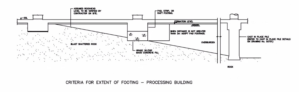
4. Foundations for innovation
Reclaimed land beneath the terminal was still settling when construction began, requiring some ingenious engineering from the foundations team.
Everything about the design and construction of Hong Kong’s new terminal was accelerated. The pressure to find faster ways to design and deliver was particularly acute when it came to the foundations, which were on the critical path for every other activity.
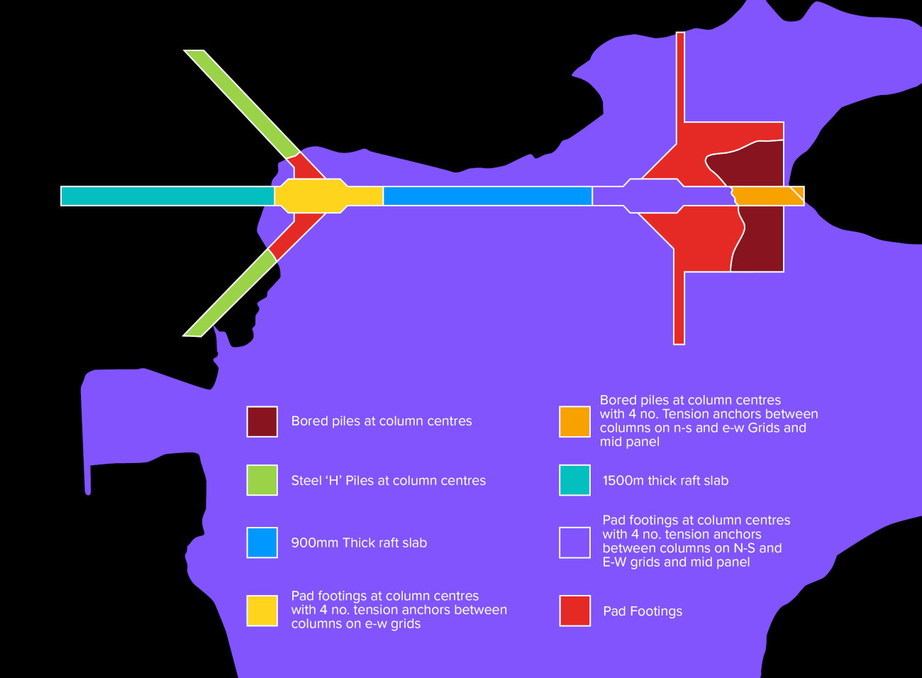
The east part of the new terminal, accounting for about 60% of its overall footprint, would be founded in the hard granite of Chek Lap Kok Island. However, the concourses to the west would be built on land recently reclaimed from the sea – loose material placed on top of alluvial sands and silts. The reclamation was soft and still settling. These very different ground conditions required drastically different foundation approaches, complicated by local variations across each part of the site.
A wide range of foundations types were called for, including pads with tension anchors to resist uplift, strip footings, steel H-piles, raft slabs, and bored reinforced concrete piles up to 50m deep.
Pioneering parametric design
“We used an early form of parametric design,” says David Mepham, now a major projects principal for Mott MacDonald. “We didn’t know exactly what ground conditions would be encountered across the site until the basement had been fully excavated. So we set out parameters and matched the right solution to the conditions once we knew exactly what we were dealing with.”
Across the granitic rock of Chek Lap Kok island, the team encountered igneous intrusions, weathering, a major fault and blast shattering caused by quarrying of the island. Close to the former shoreline there were former rice paddies. And across the reclamation area, the depth of firm underlying strata for end-bearing piles varied, typically between 10m and 20m, but down to depths as great as 50m.
“We developed solutions that were largely interchangeable depending on whether the interface was with the hard rock or the soft reclamation.”
The foundations supported a reinforced concrete basement slab that varied in thickness from 600mm to 1,400mm.
Under pressure
The basement was so deep that it was immersed 5m below sea level. “That meant that there was a lot of water pressure trying to push it up out of the ground,” says David.
Traditionally the solution would have been to thicken the base slab but David knew that this wouldn’t work. “The level of the basement and foundations was determined by the arrivals and departures requirements, meaning that it was fixed.” Any increased depth would need to be taken downward in order to maintain the level of the structures above, thereby displacing more water making the uplift force higher. To solve the problem, David and team employed tension anchors.
Each tension anchor consisted of four 40mm steel bars grouted into a 140mm diameter tube drilled into underlying rock. The anchors were arranged on a 6m grid. Where the grid pattern of the anchors overlapped with piled foundations, the anchor was omitted, as the pile would instead take both compressive and tension loading.
Bearing capacity challenge
The team also had to work out the bearing capacity of the blast-shattered granite. “There were no guidelines on how to assess blast fragmented rock. Our innovation was to use a system of rock mass rating to derive a figure for the rock quality,” says David. “We succeeded in getting a relatively high bearing capacity of 2MPa, which was which was a big win,” enabling savings to be achieved on foundation design.
5. Shaping new environmental legislation
Our work on Chek Lap Kok airport was fundamental in shaping new legislation for environmental impact assessment.
In the decades before the airport work began in the 1990s we had been working with Hong Kong’s government on development studies to explore how its growing population and economy could be supported in a sustainable way.
“In those days, there was no environmental impact assessment ordinance, and that was one of the things that we were looking to support the government to develop,” says Anne Kerr, Asia executive advisor and water engineer by trade.
The Ports and Airports Development Strategy, known as PADS, advanced the environmental agenda – indeed, the government introduced its Environmental Ordinance just before the airport opened in 1998. As planning and design for the airport advanced, models were developed for environmental and ecological impact evaluation, which put the environmental design at the heart of the planning process.
“It was a significant piece of legislation, and I think many of us who worked in environmental and water aspects helped shape the legislation by doing technical methodology papers and technical memoranda that are now embedded in the legislation,” says Anne.
Having established that it would be impossible to meet demand by expanding the original airport at Kai Tak, the team began working on development plans for the preferred option of development at Chek Lap Kok and North Lantau. As a water specialist, Anne focused on water quality and hydrodynamics, designing in solutions that minimised environmental impacts.
This included designing in a 200m wide self-flushing sea channel between the new airport land mass and the existing Lantau Island. This was important because along the north shore of Lantau Island there was a sewage treatment outfall: preventing free dispersion by ocean currents could have created stagnation and odour issues, which had been experienced elsewhere in Hong Kong in the past.
The road, rail and utilities connections between Launtau and Chek Lap Kok islands were carried on new bridges that also solved a drainage challenge. During heavy rainfall, large volumes of water run down the hillside. The bridges allow the water to flow unimpeded, avoiding the need to construct drainage channels and culverts.
“We were thinking about climate change, rising sea levels and the role that nature-based solutions could play to mitigate this back in the 90s, long before it became a widely recognised consideration for infrastructure projects,” continues Anne.
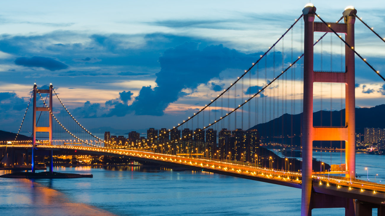
6. Tsing Ma: designing the world’s longest road and railway suspension bridge
The Tsing Ma suspension bridge built on decades of experience in developing the aerodynamic performance of long span structures. For nearly two decades it held the record as the world’s longest dual road and rail crossing.
Designers of the fixed link between Hong Kong and Lantau Island faced a major challenge: to make it aerodynamically stable in typhoon winds of up to 350km/h. This would have been a tall order for a road only bridge. The complication for the team responsible for Tsing Ma was the need to accommodate rail as well as road, requiring a much deeper deck, and presenting a significant aerodynamic challenge.
To solve it we brought decades of experience in suspension bridge design.
Framing the challenge
Our work on the crossing began in the late 1970s when politicians were contemplating developing the island of Lantau and connecting it with the city. In 1977 we worked on a feasibility study for the new crossing. Bored tunnels, immersed tube tunnels and long span bridges were all investigated. The study concluded that a bridge crossing was the most appropriate solution.
The Lantau Fixed Crossing, as it was then known, comprised a high-level crossing of the Ma Wan Channel between Tsing Yi and Ma Wan Island and the crossing of the Kap Shui Mun channel between Ma Wan and Lantau islands. A dual bridge solution was recommended and accepted.
Only a high-level suspension bridge with a span of around 1400m would be able to clear the Ma Wan channel, the only deep sea navigation channel leading to the economically important Pearl River in southern China, and this dictated the navigational clearances required for the bridge.
Kap Sui Mun was much smaller and would only need a cable stayed bridge with a 400m span.
Jeff Young was project engineer for the Tsing Ma Bridge and resident engineer during its construction. “In the final design developed towards the end of the late 1980s, the need for a high frequency, high speed railway was paramount. It was looking to carry at least 50% of passengers from central Hong Kong to the airport by railway.” Geoff notes that due to the inherent flexibility and dynamism of suspension bridges, they had rarely been used to carry railways, for which stiffness and stability are desirable. “That presented a number of significant challenges.”
Aerodynamic solution
Geoff and colleagues combined approaches used on two of the most advanced suspension bridges ever built – the Forth Road Bridge in Scotland and the Severn Crossing between England and Wales.
Earlier bridges had suffered from wind-induced oscillation, caused by turbulence. In strong winds the resulting sway, bucking and twisting of suspension bridge decks forced bridges to be closed and even caused structural damage. The Severn Bridge resolved this issue with a revolutionary box girder deck design. Not only did the strength of the box allow it to be shallower in section than preceding truss girder designs; the outer edges of the box were tapered. Cross-winds blew across the deck smoothly – the deck performed a bit like an aeroplane wing in flight. Designers of the Forth Bridge took a different approach to the turbulence challenge. The deck had a longitudinal slot or vent down its centre that allowed differential air pressures above and below the deck to partially balance, reducing the turbulence on the downwind side.
“The combination of putting what the Severn had achieved with its aerodynamic shape together with the venting through the deck that we designed into the Forth to relieve pressure, was something that hadn’t been done before,” says Jeff. It worked.
Track innovations
Railways need a stable track with minimal movement, but suspension bridges are inherently flexible. As a train moves over the bridge it pushes the suspended deck down: the train creates a wave of movement ahead of itself. Wind loading also creates side-to-side movement. And bridges expand and contract longitudinally, requiring joints to accommodate thermally induced movement – predicted to be up to 1.1m.
To satisfy the railway’ stringent deflection and rotation control criteria, the bridge deck was made continuous between anchorages – a distance of 2.16km. Specially designed rail movement joints were located at each end of the deck to accommodate longitudinal and angular movements.
Angular movements were controlled by supporting the bridge’s side spans on piers. These prevented the side spans from sagging when loaded by passing trains. And by working in tension as well as compression, they helped to reduce sag in the main span as well. The side piers also served to control horizontal movement caused by wind-induced side-to-side sway of the main span.
Another important innovation was the design of a unique trackform which could absorb the vibrational energy of the trains, minimising impact on the structure and noise propagation. It involved a lightweight steel grid mounted on resilient rubber bearings that were tuned to absorb the vibration of wheels on rails.
Tsing Ma key stats
-
2160mtotal length
-
1377mmain span
-
206mtall towers of slipformed reinforced concrete
-
140km/hrailway design speed
-
62mship clearance height
-
50mdeep anchorages
-
1.1mdiameter main cables, spun using 160,000km of galvanised steel wire
-
500,000m³concrete used in construction
-
50,000tstructural steel
-
Five-yearconstruction schedule
7. Keeping HKIA at the leading edge
From the moment Hong Kong International Airport opened in 1998 the number of passengers and tonnes of freight handled began to soar. We have continuously supported the airport authority to provide increased capacity alongside a quality of passenger and customer experience that airports worldwide aspire to match.
Two key additions to the airport were the North (Terminal 1) Satellite Concourse, opened in December 2009, and the Midfield Concourse, opened in March 2016.
North Satellite
With an initial capacity of 5M passengers per annum, the North Satellite Concourse increased the airport’s overall passenger capacity by more than 10%.
It provided 10 aircraft stands specifically for narrow bodied planes serving the short haul market, which grew rapidly in the noughties. It enabled the airport to maintain its service pledge of embarking and disembarking more than 90% of its passengers via air bridges, providing a weathertight indoor environment.
A key challenge was fitting the new stands into the space available. Taxi lanes on three sides made space tight. It was impossible to follow conventional stand design and park planes square to the building. To accommodate them we developed a solution that parked planes at an angle, only 3.5m from the concourse building. A bespoke ‘zigzag’ air bridge design was developed to provide an acceptable ramp gradient within the very limited space available.
The concourse building itself presented challenges: remote from the main terminal, it required its own supplies of conditioned air, fire services and low voltage electricity. These were accommodated in a rooftop ‘pod’.
Because air traffic control requires clear sightlines across the airport, height restrictions were imposed on the building. Rooflines were sculpted to shave the building in under the sloping height limit. The building matched the architectural, performance and sustainability standards set by Terminal 1.
Working in a busy airside location with heavy demand on aircraft stands called for careful control of construction risks. This was done through comprehensive ground investigation and by using building information modelling for services and structural clash analysis – BIM was at that time a significant design innovation. The model was also used for construction planning.
Midfield Concourse
Sandwiched between the airport’s two runways, the Midfield Concourse provided an extra 15% capacity – 10 passengers/year.
“Numerous factors contribute to HKIA’s success – it’s easy to find your way around, it offers fast, efficient service, architecturally it’s fantastic and it has great facilities. It’s a pleasure to use,” said David Mepham in 2015, when he was project director responsible for the concourse. With the Midfield Concourse we set out to uphold these standards.
Work on the project started in 2008 with master planning; we guided the project through preliminary design and detail design phases, the latter in joint venture with Arup.
To make best use of the space-constrained site, we examined 14 configurations for the concourse building. Laying it out as an X, H or K would have provided a larger number of pier-served aircraft stands, but aircraft would have had to manoeuvre out of cul-de-sacs and taxi around the building to reach a runway on the far side.
“Looking at aircraft movements, these configurations would have resulted in complex flows,” comments David. “To create more efficient aircraft movements we adopted an I-shaped building, with aircraft taxiing alongside to reach their desired destination.”
This I-shaped configuration provided 20 ‘frontal’ aircraft parking stands, enabling passengers to embark and disembark aircraft via air bridges, plus was a new apron and taxiway.
At its midpoint, we widened the building to provide a central ‘node’. It is an exciting space with a full-height atrium to provide travellers with a sense of arrival. “In a large building it’s important to have a visible reference point for wayfinding,” says David. The node houses retail and catering outlets.
We carried out detail design using BIM to integrate multiple design disciplines – civil, structural, mechanical and electrical, airfield and façade design. At the time it was in the vanguard of digital delivery.
The project was also agenda-setting in its environmental performance:
- High performance glazing in the floor-to-ceiling façade reflects 40% of solar heat, reducing the use of air conditioning.
- North facing skylights bring natural light into the centre of the building.
- Low energy lighting with daylight sensors reduces energy consumption.
- Recycled water cools the chillers providing air conditioning.
- Solar photovoltaic panels on the roof meet a proportion of the building’s energy needs.
- Achieved Gold status under Hong Kong’s BEAM Plus sustainability assessment and accreditation system.